
Key Takeaways
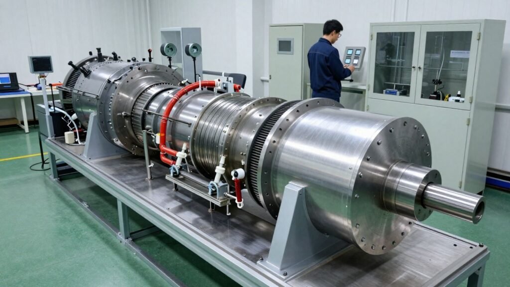
A gearbox performance test turns assumptions about a transmission into measured evidence. The most useful programs connect clearly defined limits with repeatable measurements taken under realistic conditions.
- Define speed, torque, temperature, efficiency, noise, vibration, and accuracy targets before testing.
- Inspect and calibrate the gearbox, lubricant, sensors, and test bench before applying load.
- Combine no-load, rated-load, transient, and operating-range tests rather than relying on one run.
- Record stable, traceable data so abnormal heat, vibration, backlash, or power loss can be investigated.
- Compare every result with specifications, acceptance criteria, and a trustworthy baseline.
What a gearbox performance test measures
A gearbox performance test examines how effectively and consistently a transmission converts input motion into useful output. It can expose losses that are invisible during a brief visual inspection, from excess friction to poor alignment. The test should measure both immediate performance and signs of developing reliability problems. That makes the result useful for design validation, commissioning, maintenance, or failure analysis.
Torque, speed, and power transmission
Torque and rotational speed are the foundation of the test because they define the mechanical work entering and leaving the gearbox. Measure both shafts under the same time reference, then check that the ratio and direction agree with the design. Sudden changes may point to slip, coupling problems, control instability, or a mechanical fault rather than a gear problem alone.
Input and output power can be calculated from torque and angular speed. A speed sweep is often more revealing than a single operating point because it shows where the gearbox behaves normally and where losses or instability begin. Record the load, direction, gear stage, and sampling rate alongside each reading.
Efficiency and power loss
Efficiency compares useful output power with input power, while power loss is the difference between them. Losses arise from gear mesh friction, bearings, seals, churning lubricant, and auxiliary systems. Since these effects change with speed, load, and temperature, an efficiency claim without its test conditions is difficult to interpret.
A practical test repeats selected points after temperatures stabilize. If efficiency improves as the lubricant warms, viscosity and churning may be influential; if it declines with temperature, clearance, sealing, or lubrication issues deserve attention. Use the same calculation method throughout the test so comparisons remain meaningful.
Noise, vibration, and temperature
Noise and vibration provide clues about mesh quality, imbalance, looseness, bearing condition, and alignment. Temperature adds a slower but valuable signal: a gearbox that reaches an unusual equilibrium temperature may be losing power internally or receiving inadequate lubrication. Measure at defined locations, not just wherever a probe is convenient.
The signals should be time-stamped with speed and load. A vibration peak that appears only at one mesh frequency means something different from broadband vibration that rises across the whole operating range. Likewise, a hot bearing housing and a hot oil return suggest different next steps.
Backlash, accuracy, and repeatability
Backlash is the lost motion between reversing input and output direction. Measure it at a defined torque, position, and temperature because housing expansion and contact conditions can change the result. Positioning accuracy and repeatability matter especially when the gearbox is part of a servo or indexing system.
Run several cycles rather than accepting one favorable reading. The spread between repeated measurements can reveal fixture flex, sensor resolution limits, inconsistent preload, or a gearbox that is not mechanically stable. Low backlash alone is not enough if the measurement cannot be reproduced.
How to prepare for gearbox testing
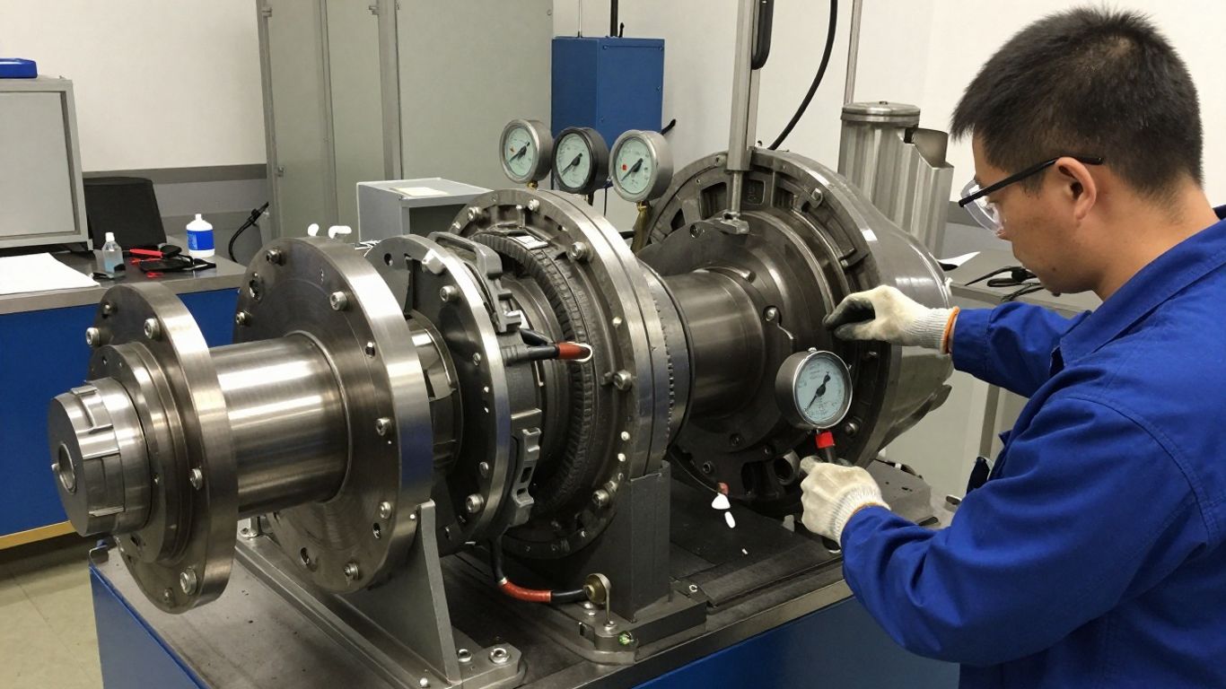
Preparation determines whether a test measures the gearbox or the test arrangement. Write down the purpose, operating envelope, acceptance limits, and evidence required before connecting the drive. A careful setup also makes failures safer and prevents an expensive retest caused by a missing sensor or undocumented lubricant.
Defining the test objective and acceptance criteria
State whether the test is for design verification, production release, commissioning, condition assessment, or troubleshooting. Each purpose calls for different dwell times, loads, and recorded variables. Acceptance criteria should include tolerances, measurement uncertainty, stabilization rules, and what constitutes an abort.
A useful protocol identifies the exact gearbox configuration and duty cycle. It also explains how to handle a result that falls outside the limit: stop, repeat, inspect, or continue under controlled observation. This prevents decisions from being improvised after an alarming reading appears.
Selecting the gearbox, lubricant, and operating conditions
Confirm the part number, ratio, mounting orientation, seals, bearings, and coupling arrangement before the run. Use the specified lubricant and document its grade, batch if relevant, fill level, condition, and filtration. Speed, load, ambient temperature, cooling, and duty cycle should match the intended application unless the test deliberately explores a boundary.
Extreme environments need their own plan. For example, low-temperature planetary testing describes why cold operation can affect efficiency and reliability in demanding applications. That kind of condition should be reproduced only with suitable thermal control and a clearly defined measurement sequence.
Inspecting components before the test
Inspect gears, shafts, bearings, seals, fasteners, couplings, and the housing for damage, contamination, incorrect assembly, or signs of previous distress. Check shaft runout and mounting faces where alignment could influence the result. Photograph unusual marks and record what was found before the gearbox is energized.
The baseline should include free rotation, lubricant appearance, external condition, and any pre-existing backlash or vibration readings. Small details matter: a loose guard, a damaged keyway, or a blocked breather can create a test result that looks like an internal failure.
Calibrating sensors and measurement equipment
Calibrate torque, speed, temperature, pressure, vibration, and acoustic channels within the range they will actually experience. Verify polarity, zero drift, channel identity, sample timing, and data acquisition settings. A calibration certificate is useful, but a pre-test system check is equally important because wiring and fixture errors occur after calibration.
The measurement chain should be checked under a known condition where possible. Record sensor serial numbers, calibration dates, ranges, filters, and uncertainty. Clear documentation, similar to the OKR implementation method, keeps objectives and measurable results connected, although a gearbox protocol still needs mechanical acceptance criteria of its own.
Which gearbox performance tests to run
No single test covers every failure mode. A sensible sequence begins gently, moves through rated conditions, and then examines the transitions that a real machine imposes. Select tests according to the gearbox duty cycle rather than treating a standard sequence as universally sufficient.
No-load and break-in testing
No-load testing checks free running, baseline vibration, noise, speed ratio, oil circulation, and temperature rise without the full working torque. It is useful after assembly or repair because abnormal friction and rubbing may appear before load is applied. Break-in testing can then allow contact surfaces and lubricant distribution to settle under controlled conditions.
Do not treat a quiet no-load run as proof of load capability. Log run-up behavior, coast-down behavior, temperature trend, and any changes in sound. If the signal changes during break-in, record when it changed and inspect the lubricant and housing afterward.
Rated-load and overload testing
Rated-load testing establishes whether the gearbox delivers the specified torque and speed while remaining within thermal, vibration, noise, and efficiency limits. Increase load in controlled steps and hold each point long enough to obtain stable readings. Overload testing should be justified by the design requirement and bounded by a defined stop condition.
The load path must be checked as carefully as the gearbox. A flexible coupling, dynamometer, or fixture can distort torque or introduce bending loads. Results from automated gearbox testing illustrate why controlled fixtures and repeatable procedures are valuable when stiffness, efficiency, and backlash are being evaluated.
Low-speed and high-speed testing
Low-speed tests reveal stiction, uneven torque, positioning error, lubrication limitations, and sensitivity to backlash. High-speed tests stress balance, bearing condition, windage, churning, seals, and thermal management. Use appropriate ramp rates and guarding because the risks are different at each end of the range.
Test points should include the normal operating speed and carefully selected margins around it. Do not extrapolate high-speed performance from a low-speed result. If cold operation is part of the application, include a controlled thermal soak rather than simply starting the gearbox in a cold room.
Directional, start-stop, and transient testing
Reversals, repeated starts, emergency stops, and rapid load changes can reveal behavior that steady-state testing misses. Measure acceleration, torque peaks, output position, vibration, and recovery time during each event. The control system’s limits should be separated from the gearbox’s mechanical limits in the test record.
Use a repeatable profile with defined dwell times and event counts. Compare the first and last cycles for drift, rising temperature, or increasing backlash. A transient result is most useful when the same profile can be run again after an adjustment or repair.
How to measure gearbox performance accurately
Accuracy depends on more than choosing high-resolution instruments. Sensors must be correctly located, aligned, synchronized, and protected from the environment. The test team also needs a plan for filtering, averaging, uncertainty, and the distinction between a real mechanical signal and an artifact from the bench.
Using torque and speed sensors
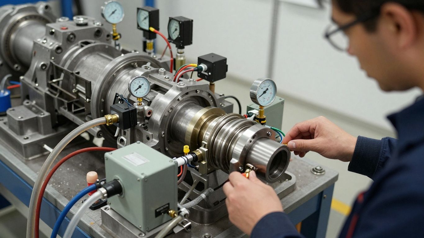
Install torque sensors where they see the intended load without excessive shaft bending or coupling misalignment. Speed sensors should provide a stable reference on the relevant shaft, and both channels must share reliable timing. Check zero values before and after the run to identify drift.
Torque ripple can be valuable, so avoid smoothing it away before deciding what the test is meant to reveal. Use a sampling rate and filter appropriate to the gear mesh and transient events. The gearbox test run parameters offer a useful example of the range of measurements that may be monitored, including input speed, power loss, temperature, vibration, and oil behavior.
Monitoring temperature and lubricant condition
Place temperature sensors at the sump, inlet and outlet where applicable, housing, and bearing locations that matter to the design. Track ambient conditions and cooling flow at the same time. Temperature should be logged continuously enough to show both rapid excursions and the eventual stable trend.
Inspect lubricant for particles, discoloration, foaming, water, or an unexpected odor when the procedure permits. Oil pressure and flow can reveal a supply problem before the gearbox itself becomes visibly hot. Never interpret temperature alone without considering fill level, viscosity, airflow, and load history.
Collecting vibration and acoustic data
Mount accelerometers firmly and document their axes and locations. Capture overall levels as well as frequency content when diagnosing mesh, bearing, imbalance, or alignment conditions. Acoustic measurements require a controlled microphone position and attention to reflections from guards, walls, and nearby machinery.
A baseline taken on the same bench is especially useful. Live vibration monitoring describes a facility approach that records bearing temperature, speed, vibration, noise, and oil variables during a test run. That example should inform measurement planning, not replace the acceptance criteria for the gearbox under examination.
Recording efficiency across the operating range
Calculate efficiency at multiple combinations of speed, torque, and temperature instead of quoting one number. Keep the operating point long enough for transient effects to settle, but retain the raw data so short events are not hidden by averaging. Repeat points near the expected peak and near the boundaries of normal operation.
Present the result as a traceable set of conditions, not an isolated percentage. A useful report states the input and output measurement methods, uncertainty, lubricant, ambient temperature, stabilization rule, and any excluded data. This makes small changes in efficiency easier to assess during later maintenance.
How to conduct the test step by step
A repeatable gearbox performance test follows a controlled path from inspection to shutdown. The operator should know which values are observed continuously, which are checked at intervals, and which trigger an immediate stop. Written sequencing reduces both unsafe improvisation and gaps in the final evidence.
Setting up the dynamometer or test bench
Mount the gearbox on a rigid, correctly aligned fixture and connect the drive and load machine without forcing the shafts into position. Install guards, lubrication lines, cooling equipment, drains, sensors, and emergency stops before energizing the system. Confirm that the bench can absorb the planned torque, speed, and stored energy.
Run a static check of fasteners, couplings, cable routing, sensor zeroes, and oil circulation. The setup should allow the gearbox to expand as designed without imposing unintended restraint. A short low-energy rotation can verify direction and clearance before the main sequence begins.
Applying controlled speed and load profiles
Start at the lowest safe condition and increase speed or torque according to the approved profile. Change one major variable at a time where practical so the effect of each step remains clear. Pause when a reading moves unexpectedly rather than rushing to the next point.
The operator should record commanded values as well as measured values. Differences between them can expose controller limits, slippage, or dynamometer calibration issues. During transient tests, use a synchronized trigger so peaks are not lost between separate recording systems.
Stabilizing operating temperatures
Allow the gearbox to reach a defined thermal condition before judging steady-state efficiency or temperature rise. Stabilization may mean a specified temperature slope over a specified period, not merely waiting an arbitrary number of minutes. Keep cooling, ambient conditions, and lubricant flow consistent between comparable runs.
If the temperature continues to climb, stop and investigate rather than extending the dwell indefinitely. A stable but unusually high temperature is still a finding. Mark thermal transitions in the data so later reviewers can distinguish warm-up from normal operating behavior.
Logging data and documenting test conditions
Log every channel with a common timestamp and preserve raw files alongside processed calculations. The record should include gearbox identity, assembly state, lubricant, sensor details, fixture configuration, speed and load profile, ambient conditions, alarms, pauses, and operator observations.
A report becomes much easier to audit when it separates measured data, calculated values, and interpretation. The same discipline used in content performance reporting can help organize evidence, but mechanical measurements must remain the primary source for gearbox conclusions. Include photographs and a deviation log when the test differs from the approved procedure.
How to interpret gearbox test results
Interpretation starts with relationships between measurements, not isolated pass-or-fail numbers. A rising temperature paired with falling efficiency tells a different story from rising temperature with unchanged power loss. Review the sequence, operating point, uncertainty, and baseline before assigning a cause.
Calculating torque, power, and efficiency
For rotational systems, mechanical power is torque multiplied by angular speed. If speed is recorded in revolutions per minute, convert it consistently before calculating watts. Efficiency is output power divided by input power, expressed as a percentage, while power loss is input power minus output power.
Check sign conventions during reversals and exclude invalid samples according to a documented rule. Small differences between input and output power can be comparable to sensor uncertainty at low load. That is why repeatability and uncertainty should accompany every reported efficiency value.
Identifying abnormal heat generation
Compare the temperature slope, stabilized temperature, and location of the hottest point with the baseline. Excess heat may result from excessive preload, poor alignment, seal drag, lubricant problems, blocked cooling, or an overloaded gear mesh. A local bearing temperature rise is more diagnostically useful than a single average housing temperature.
Look for supporting evidence in torque, vibration, oil flow, and noise. If heat rises while output torque falls, internal friction or lubrication failure becomes more plausible. If the whole bench warms similarly, verify the cooling and ambient measurements before condemning the gearbox.
Distinguishing gear, bearing, and alignment faults
Gear faults often correlate with mesh-related frequencies, torque ripple, or a repeating pattern tied to tooth engagement. Bearing faults may produce characteristic vibration changes and localized temperature rise. Alignment problems can affect vibration, coupling loads, shaft temperature, and the stability of readings across speed.
These patterns are clues, not automatic diagnoses. Confirm them by checking mounting, coupling, preload, lubrication, and sensor installation. A controlled repeat after correcting the bench can prevent a fixture defect from being misidentified as an internal component failure.
Comparing results with specifications and baseline data
Compare like with like: the same lubricant, temperature, speed, load, mounting orientation, measurement method, and stabilization rule. Mark results that are outside the declared test envelope rather than quietly mixing them with normal points. Specifications define acceptance, while baseline data often helps explain whether a change is gradual or sudden.
A result just inside a limit may still deserve attention if the trend is worsening. Conversely, a small difference outside a limit may be explained by measurement uncertainty or a documented setup deviation. The report should state the evidence for the decision and recommend a repeat, inspection, or release.
Standards, safety, and troubleshooting considerations
Standards provide a common language for test conditions, ratings, measurement methods, and reporting, but they do not remove the need for engineering judgment. Safety controls must be in place before the first rotation because high-speed shafts and stored energy can turn a minor setup error into a serious event. Troubleshooting should proceed from the simplest external causes toward internal inspection.
Applying relevant gearbox testing standards
Identify the standards that apply to the gearbox type, industry, contract, and intended use, then record the edition and clauses used. Do not cite a general quality-management standard as if it were a complete mechanical performance procedure. The gearbox testing standards guide is a useful starting point for considering international and industry-specific requirements, including gear design and performance evaluation.
The protocol should state which requirements are mandatory and which are supplementary. Include definitions, test tolerances, calibration expectations, reporting format, and retest rules. If a customer specification conflicts with a general standard, resolve that difference before testing.
Protecting operators and test equipment
Use fixed guards, interlocks, emergency stops, exclusion zones, and suitable hearing protection where required. Keep loose clothing, tools, cables, and hands away from rotating parts, and never bypass a safety device to obtain a reading. Confirm that the bench, foundation, couplings, and containment can withstand the maximum planned event.
Control access during energized testing and establish a clear communication method between the operator and observers. A stop should be treated as a safe state, not as an invitation to approach immediately; rotating components may continue to coast and hot lubricant may remain pressurized.
Managing lubrication, sealing, and contamination risks
Use the specified fill level and lubricant condition, and verify flow, pressure, temperature, and filtration where those variables are part of the design. Keep sampling tools and containers clean. Protect open ports and breather paths from dust, water, fibers, and stray hardware.
Leaks can alter both performance and safety. Inspect seals and fittings before the run, contain spills, and stop if oil reaches a hot surface or rotating interface. After testing, examine the lubricant and magnetic plugs or filters according to the approved maintenance procedure.
Investigating inconsistent or failed results
Begin by checking the data file, sensor zero, calibration status, wiring, time synchronization, fixture alignment, coupling condition, and commanded-versus-measured speed and load. Repeat only after the suspected cause has been documented. A failed result should not be erased simply because a later run passes.
A useful troubleshooting sequence is:
- Confirm the test configuration and lubricant against the approved procedure.
- Verify sensor channels, calibration, sampling, filtering, and data timestamps.
- Inspect alignment, mounting, couplings, cooling, seals, and oil circulation.
- Compare the event with baseline vibration, temperature, torque, and noise data.
This sequence keeps the investigation evidence-based and helps separate equipment faults from measurement faults. Record the corrective action and the reason for any retest so the final conclusion remains traceable.
Conclusion
A dependable gearbox performance test is less about collecting the largest possible data set than about measuring the right variables under controlled, repeatable conditions. Clear acceptance criteria, calibrated instruments, realistic load profiles, safe operation, and disciplined interpretation turn torque, temperature, vibration, efficiency, and backlash readings into a useful reliability decision.
Frequently Asked Questions
What is a gearbox performance test?
It is a controlled evaluation of how a gearbox transmits torque and speed, manages power loss and heat, and behaves for noise, vibration, backlash, accuracy, and repeatability under defined conditions.
Why test a gearbox before installation?
Pre-installation testing can reveal assembly, lubrication, alignment, sensor, or component problems before the gearbox is connected to the larger machine, where diagnosis may be slower and more expensive.
Which measurements are most important?
Torque, speed, input and output power, efficiency, temperature, vibration, noise, lubricant condition, and backlash are common core measurements. The exact combination depends on the gearbox and duty cycle.
How long should a gearbox test run?
There is no universal duration. The run should last long enough to complete the required speed and load profile and to establish the defined thermal stabilization condition, with additional time for transient or endurance requirements.
What causes excessive gearbox temperature?
Common causes include overload, excessive friction, incorrect lubricant, low or high fill level, poor oil circulation, blocked cooling, seal drag, bearing preload, and misalignment. Confirm supporting measurements before selecting a cause.
How can gearbox test results be made repeatable?
Use the same fixture, lubricant, sensor locations, calibration checks, operating profile, stabilization rule, sampling method, and reporting format. Preserve raw data and document every deviation.
What should a gearbox test report contain?
It should identify the gearbox and setup, state the objective and acceptance criteria, describe instruments and calibration, list operating conditions, present raw or traceable processed results, record deviations and alarms, and explain the final decision.